ASN-128
RT-1193/ASN-128 and RT-1193A/ASN-128 Doppler system antenna unit.
The ASN-128 system uses Doppler radar as its primary sensor. The movement of the aircraft across the earth is detected by four microwave beams which are radiated from the antenna and reflect back from the ground. The beams radiate out in four directions and reflect back from the ground with a slightly altered frequency due to the relative movement of the aircraft. The right front, left front, right rear, and left rear beams strike the earth under the helicopter at an angle which causes a change in the frequency of the reflecting energy if the aircraft is moving. The physical laws of the Doppler-effect relate the actual change in frequency to the velocity of the aircraft. Thus, the true velocity of the aircraft across the earth can be calculated regardless of wind speed and direction.
The four beams are periodically sampled, one at a time, and analyzed for frequency shift. When flying normally, the two forward beams reflected signal will show an increase in frequency and the two aft beams will show a decrease. If sideways or even rearward movement exists, the frequency shift of the beams will tell the story. The computer combines this information with other information available in the aircraft including: heading, pitch, roll, and true air speed. These are available from the air data computer and heading reference systems.
The computer in the ASN-128 system combines these inputs with the analysis of the four beams and derives a complete navigation picture. The pilot only has to select which function is required and fly the helicopter. The advantage of the system is that no external navigation signals are required so navigation is not affected by jamming.
The ASN-128, in Doppler mode, is a dead-reckoning system because it has no absolute knowledge of position. Early versions require the initial position to be entered by the pilot. Later versions of the system have a GPS sensor added which greatly increases the long term accuracy.
The ASN-128 system is organized in three units. The Computer Display Unit is located in the cockpit and contains the computation and display circuitry. The pilot controls the mode of operation and reads the information from this unit.
The Signal Data Converter is a remotely mounted black box containing auxiliary circuitry including the power supply, the Doppler frequency tracking circuitry, and the synchro to digital converter. The inputs from the aircraft systems, in synchro form, are converted to digital form in this unit.
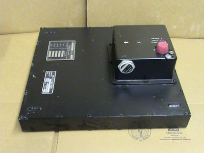
The Receiver-Transmitter-Antenna unit contains the RF circuitry including: the transmitter, the receiver, the beam switching system, the video amplifier, and the calibration factors memory. The large flat area on the bottom is the radome and is mounted flush with the belly of the aircraft. The four beams radiate from this surface.
MBT Electronics only repairs the Receiver-Transmitter-Antenna unit.